
|
|
|
| A hand shift and foot clutch was an interesting idea in 1942... I think there's probably a good reason you don't see it these days. We decided to go with a more conventional arrangement as far as gearbox, hand clutch, and left-side foot shift with a normal shifting pattern goes. We replaced the stock 3-speed transmission, its foot clutch and hand shift with a British 4-speed and a regular shifter on the left side. The transmission we selected was a pre-unit A-10 from a 60-62 BSA Goldstar. The A-10 has nice ratios and should fit into the frame without a ton of effort. Notice, of course, I say "should"...
|
| John Scerri Lytedrive P.O. Box 333 Noble Park Victoria, 3174 Australia lytedrive@optusnet.com.au |
The Lytedrive kit contains:
|
The clutch basket is a Norton style clutch with diaphragm spring rather than the four or five springs found in a Triumph or BSA clutch.
The basket has a 68 tooth, 8mm pitch ring around the outside (544mm circumference).
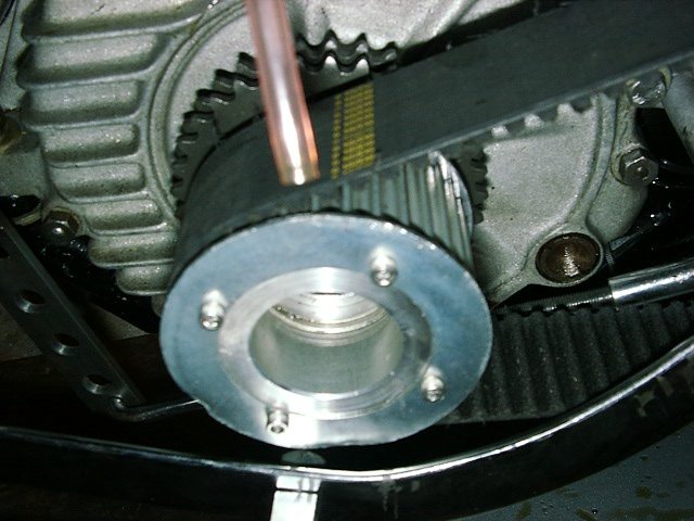 Motor
Pulley
Motor
PulleyLytedrive fabricated a motor pulley for the Harley 45" engine to match the clutch basket... but unfortunately, it didn't match the crank pin! After months of trying to get it right, we gave up and bought a regular 45 motor sprocket and bolted it to the motor pulley and were set to go. We thought about cutting off the teeth, but who knows... we might find a good use for them. Actually, they make a great item to use whcn torqueing the motor pulley to about 100 pounds. A long socket inserted into the teeth and braced against the rear footboard rod held the pulley in place while we applied the pressure. We used a 34 tooth, 8mm motor pulley for a circumference of 272mm and ratio of 2:1.
Just for posterity, the information about the original motor sprocket is included here:
| Tapered sprocket | |
| 21/32" thick (.65625") | |
| 29-31 tooth | |
| Double row |
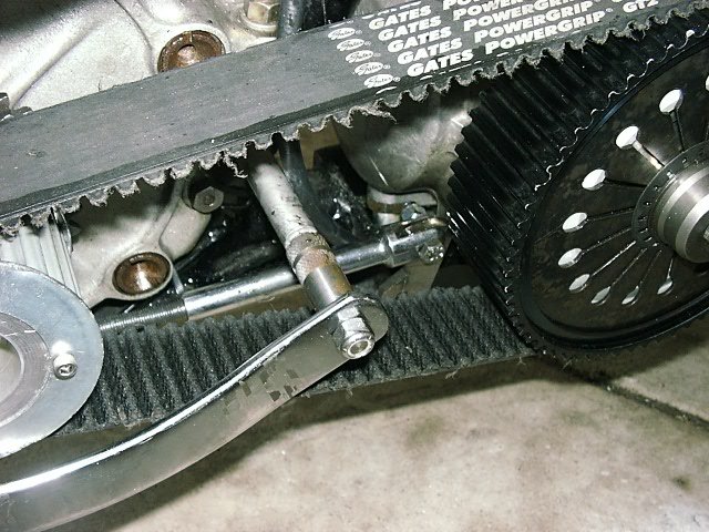 The primary drive
uses a Gates 8 960 8MGT 50mm wide belt. We had to get the
transmission close to one of the standard sizes. Based on the table here, we needed to keep the distance at 10.5" since that was about the natural distance to the transmission,
so the 270mm belt was just about perfect.
| Belt Description | Center to Center | Inches |
| 1000 Belt | 292mm | 11.496 |
| 960 Belt | 270mm | 10.629 |
| 912 Belt | 247mm | 9.724 |
| 880 Belt | 228mm | 8.976 |
However, if you look closely you'll see that we had to add an extension onto the rear floorboard mount to keep out of the belt's way. The floorboard side rail makes a nice fence too! Ahhh, the wonders of pull-it-out-of-your-ass engineering!
The shift linkage turned out to be way fun... not! The BSA transmission was a right-side shift with first up and the rest of the gears down. We wanted to use the original clutch pedal but ended up butchering the hell out of it and its hard to tell it was once the clutch pedal. You can see the shaft in an aluminum block bolted to the footboard rails. A lever drops down and goes to another lever and a crossover shaft under the frame.
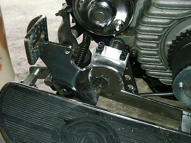
Ok, that hurt to shift so we went to...
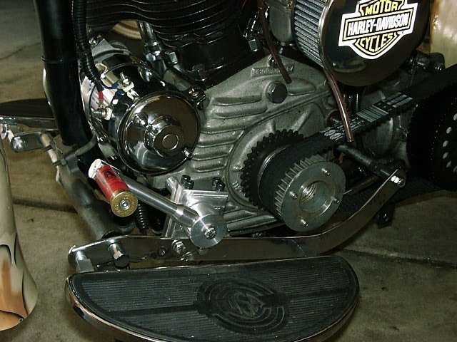
| Lever and Crossover | Crossover and Shift Lever |
 |
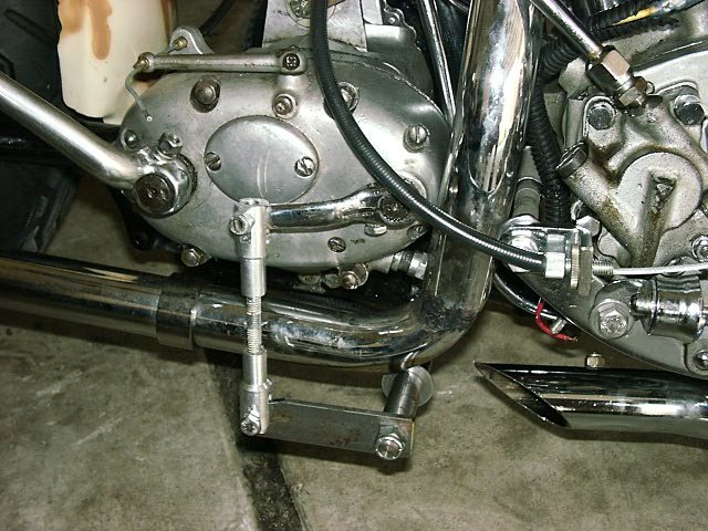 |
Ok, so it ain't the prettiest thing in the world, but it works great and gives us the left-side foot shift with first down and the rest of the gears up. After we rode it a while, the original clutch lever turned out to be a bad idea so we trashed it all together and just made a nice lever that fit your foot a little better.
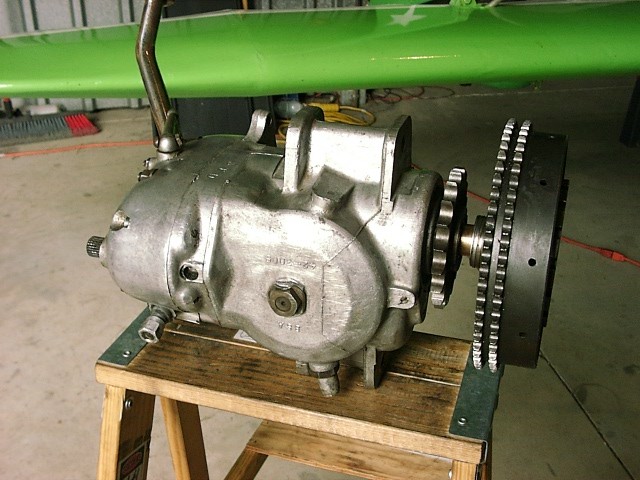 We bought a pre-unit 4-speed
A10transmission from a 60-62 BSA Goldstar.
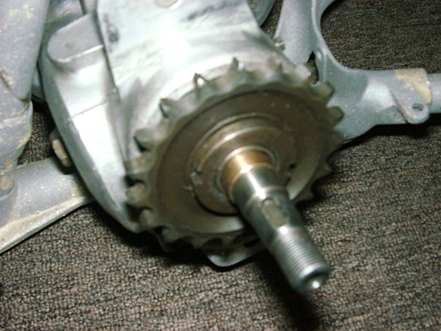
A10 Part Numbers
here
Service Manual Here
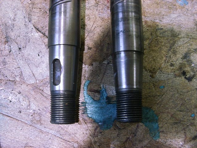 The
transmission mainshaft had to be modified a bit to fit the clutch basket and
bring it in a little closer to the gearbox sprocket. Here's a picture
of the machined shaft and a stock shaft. A flying friend of mine,
Chris Daxon, 734-678-5721, did a fantastic job of machining the taper and making a
sleeve to mate with the nut. The man's a master machinist and can do just
about anything to steel!
Below is a picture of the inside of the gearbox with the mainshaft removed. The mainshaft was a little worn so we replaced it... as well as getting an extra in case our machining didn't work out. All the gears looked in nearly new shape so we were very pleased about that. Just to keep some part numbers...
| Kickstart ratchet pinion bushing 67-3169 | |
| Kickstart ratchet spring 67-3162 | |
| Kickstart ratchet pinion 67-3376 | |
| Kickstart ratchet & mainshaft lockwasher 67-3164 | |
| Gearbox sprocket locking washer 24-4263 | |
| Gearbox sprocket 67-3065 | |
| Kickstarter spring 67-3174 | |
| Gear selector plate 67-3341 | |
| Gear selector plate spring 67-3342 |
| Gear selector plate spring washer 24-868 |
The main seal looked a little worn so we replaced that with part number 67-3067 and that stopped the oozing... Since winter was coming, we put in 550ml (400 mark) of 40w Aeroshell oil. I figure if its good enough for my airplane, its good enough here.
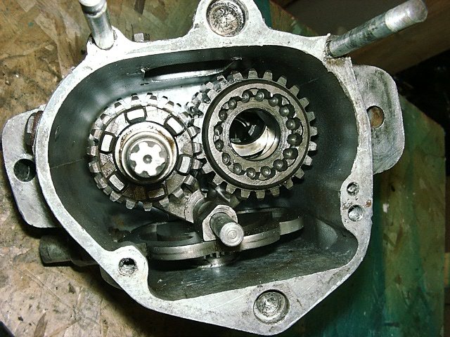
Putting the transmission back together wasn't bad... as long as you remembered where all the bits went. There were two washers that gave me a little trouble. They were the same ID but one was slightly larger on the OD and thinner. As it turns out, the thicker washer went behind 1st gear on the layshaft and the thinner one in the outer case on the mainshaft and kept the kickstart pinion gear in the proper place.
Getting the gear selector cam plate and the selector fork in the right place was a bitch!! I finally found the trick... put the thing in 4th gear and raise the selector arm so the bottom of the three teeth was centered with the arm's shaft. That took forever and two gaskets to get right.
While the transmission was apart, we cleaned it up and replaced all the gaskets with new ones. Below is a table with the gasket numbers just in case we need to open it up again.
| Outer cover | 67-3354 |
| Inner cover | 67-3346 |
| Inspection plate | 67-3033 |
| Push rod inspection cover | 29-3449 |
 Transmission Mounting
Another one of the more interesting parts... Basically, we had a box welded to the bottom of the frame, shaped it for the transmission, and drilled so a bolt could pass through the box and the bottom transmission mount. While this certainly won't let the transmission fly out, it didn't do much good for lateral movement. We considered spacers, but figured that would be WAY too hard to create so they'd fit perfectly. So, we put bolts through the frame box to "pinch" the transmission in place latterly and lock nuts to hold them in place. This also had the added benefit of allowing us to fine tune the longitudinal straightness of the transmission. Having ways to cover what you've messed up is a good thing...
Well, that was fun! First gear on the A10 is up and the rest are down, down, down. We wanted a "normal" left side shift with down for first and up, up, up for the rest of the gears. We used the original clutch lever for a shifter.
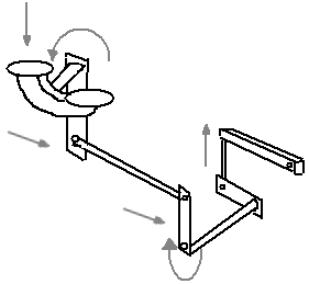 Stepping down on the front of
the clutch lever rotated the clutch lever post counterclockwise which moved a
rod rearward, that pushed a lever backward that rotated a rod under the frame
clockwise, that moved the lever on the other end up, which was attached to a rod
which connected to the shift lever on the transmission and moved it up... and
that was first gear. Opposite way, of course, for all the other gears.
Well, that was simple... all we had to do is make all the levers, rods, and connectors while dodging all the parts in the middle. Piece of cake. Its actually amazing that it works and doesn't look too much like crap either!
The A-10 transmission originally came with a 19 tooth sprocket. After we rode the bike a while we decided to change it for a larger one because: (1) The chain occasionally touched the frame and (2) The gearing was a little too low. So, we bought a new 21 tooth Gearbox Sprocket, part number 67-3064/21 (also 67-3065/21). Wouldn't you know, now the chain it too short so we had to lengthen that a link. But now, the chain has a good half inch clearance from the frame and doesn't come close to slapping it.
The gearing result was perfect! The higher gear ratio, 1:1.952 rather than 1:1.2158, seemed to be exactly what it should have been. We didn't really notice any difference starting from a standstill but there is a big difference in speed before you needed to shift. Second gear is now perfect to motor through the subdivision at a respectable speed and RPM. You don't really need to go to fourth until you reach 45-50 mph.
An added bonus was that it stopped the transmission leak too. It seems the old sprocket was worn pretty badly where it meets the main seal in the transmission. I ordered a new seal (67-3067) when I ordered the sprocket and put it in as well. However, in doing so, I did loose my automatic chain oiler! ;-)
We used a reproduction WLA rear wheel, hub, and brakes on the rear and matched it up with the gearbox sprocket on the BSA transmission. Rear sprocket has 41 teeth.
| WLA Rear Chain #530 (aka #50) 5/8 x 3/8 x .400 # links (~95 or ~59 inches). Part number 18-10108J and master link 18-20206J (Harley part 510053-65). | |
| Triumph 5/8 x 3/8 (.375) |
As I said earlier, we had originally intended to use a Triumph clutch and match that to the 45's motor sprocket but it got too complicated very quickly. I wanted to save this information just in case we needed it down the line. Here's some of the information we started with.
| Primary Chain BSA A10 1/2 x .305 | |
| Duplex Primary Chain Triumph 3/8 x 1/4? | |
| WLA 3/8" pitch, 100 link |
We started with a clutch assembly is from a pre-unit Triumph. Double row teeth on the clutch gear and an adapter to fit it to the BSA mainshaft. But looking at what it would take to make everything work, we decided to scrap it all in favor of the Lytedrive belt drive since we were going that direction anyway. It seemed like a lot of work to be thrown away later and its only money, right?
|
|